济宁博联生物科技
专注于医用耦合剂/消毒剂的生产和销售

0537-2168006
186-5379-3368
专注于医用耦合剂/消毒剂的生产和销售
0537-2168006
186-5379-3368


了解 ● 博联
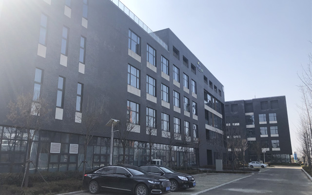
拥有自己的现代化厂房和优秀的技术的生产线/且拥有一大批专业科研技术和经营管理人才
企业简介
——
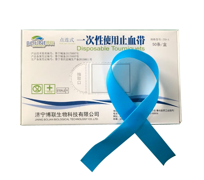
558855奔驰宝马是一家具有现代化经营管理水平和利用高科技手段专业研制、生产、加工及销售生物制品的高科技公司。主要经营项目:生物制品的研发及技术咨询,医用耦合剂,消毒剂生产和销售。建材、电子商品、化工产品(不含危险化学品),一类医疗器械的销售。拥有自己的现代化厂房和国际先进技术的生产线。且拥有一大批专业科研技术和经营管理人才。
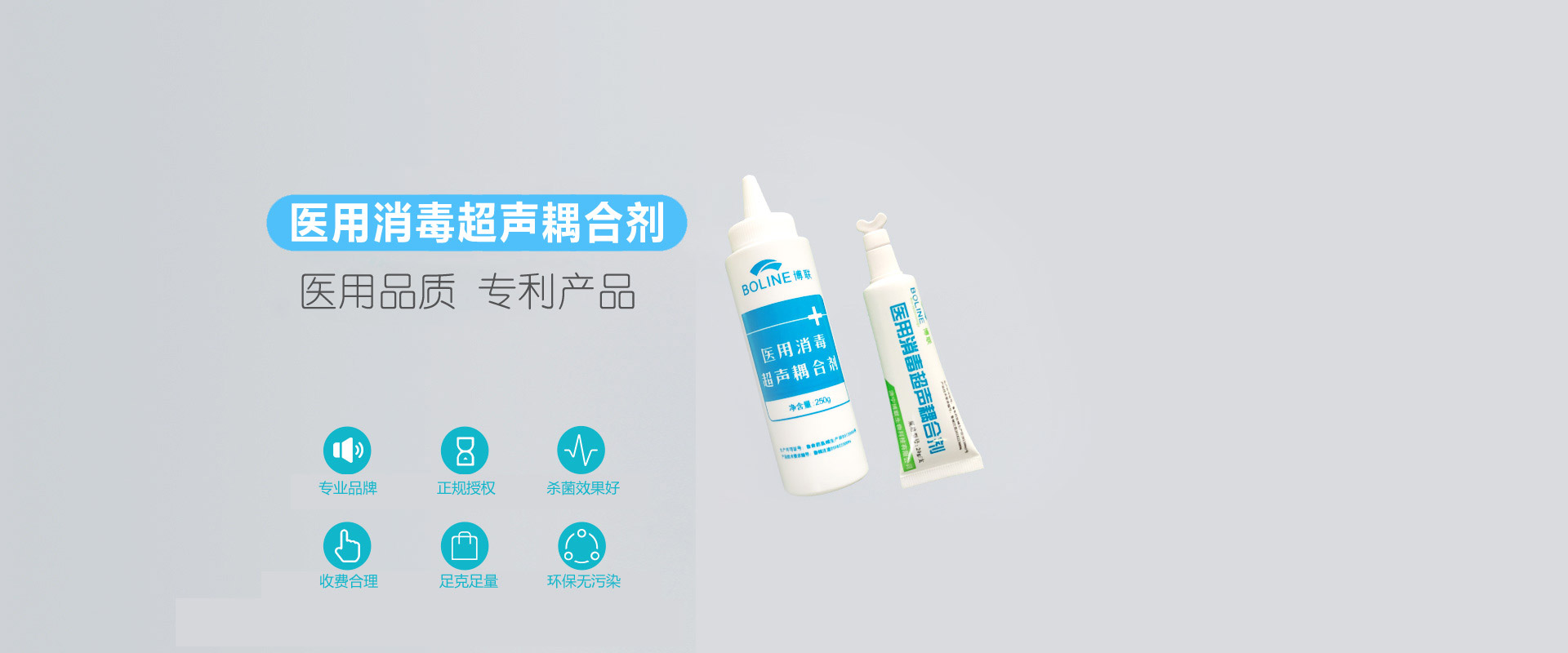
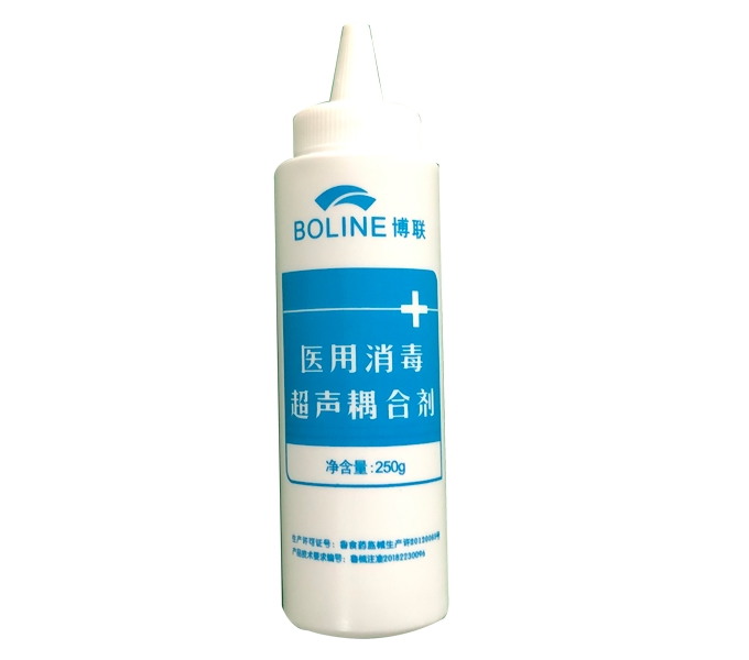
经过多年来科技研发,采用国际进口杀菌、抑菌剂,有效解决医院超声检查中的交叉感染。558855奔驰宝马研发的新一代医用消毒超声耦合剂替代传统脂溶性耦合剂,易擦洗,对皮肤无致敏,
本公司信守“产品至上、服务至上、顺应市场、造福人类”的宗旨,其研发的医用耦合剂是新一代水溶性高分子凝胶,具有图像清晰,分辨率高,对超声探头无腐蚀,并具有快速消毒抑菌作用,无异味、不留污渍,易清除。
公司竭诚欢迎广大朋友前来商谈。“诚心、务实、奋进”是我们博联人的准则,“质量、信誉、热心为客户服务”是我们永远不变的经营理念!
NEWS INFORMATION
558855奔驰宝马
——
![]()

首先我们全面认识医用超声消毒耦合剂的使用原因:超声检查时,探头与病人皮肤之间的空气将阻碍超声波传入人体,为获得高质量的图像,需要液性传到介质来连接探头与病人体表,这种介质就是耦合剂。……

超声耦合剂被广泛运用在医院在做超声波检查身体。超声耦合剂,它的功能主要是使超声探头与皮肤接触更密切。因为医用超声波频率为2.5-5M,不能在空气中传导。如果探头与皮肤中存在……

耦合剂在医用中的运用原理是什么呢?医用所用的超声波频率为2.5-5M,是不能在空气中传导的。在对人体进行检查时,如果探头与皮肤之间存在有空气,超声波一旦遇到气体就……
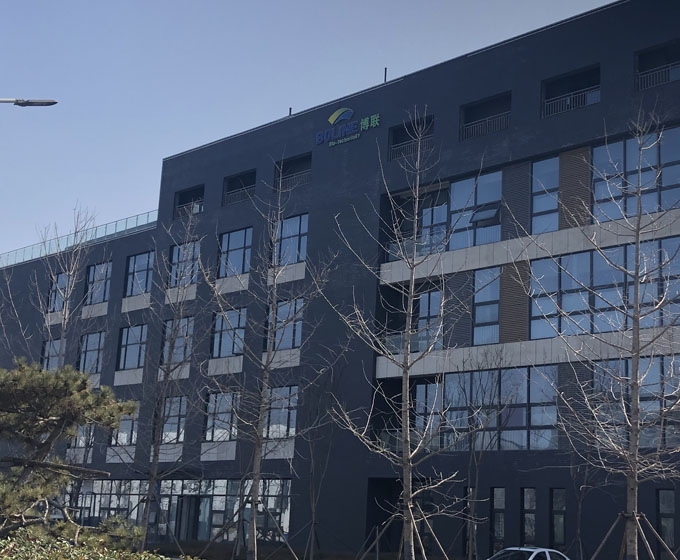
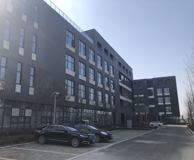
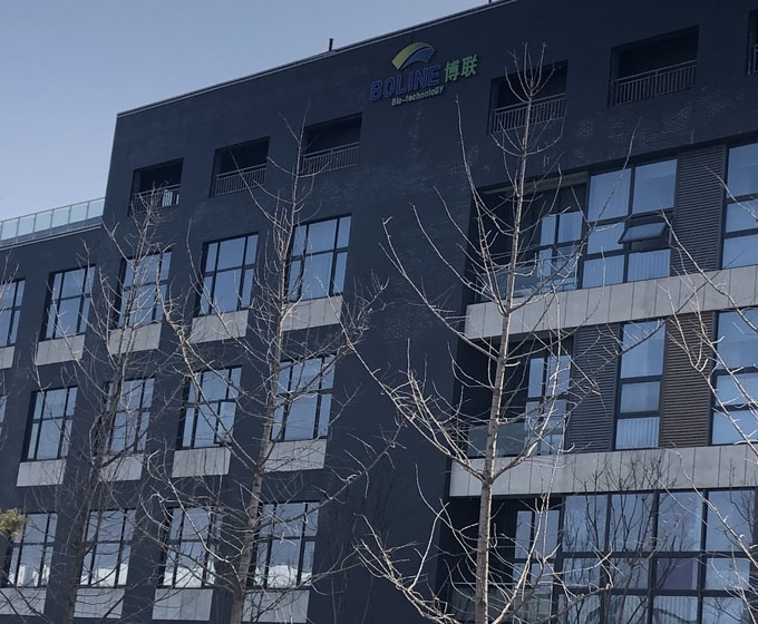
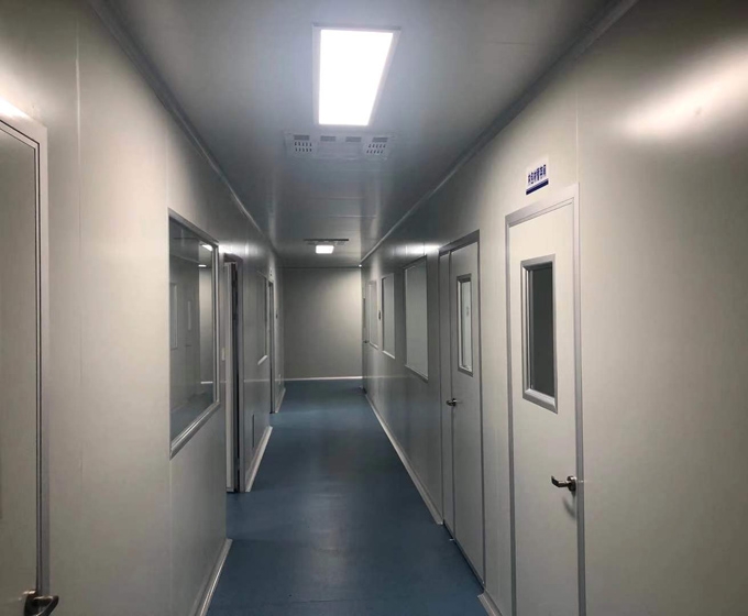
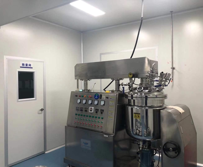
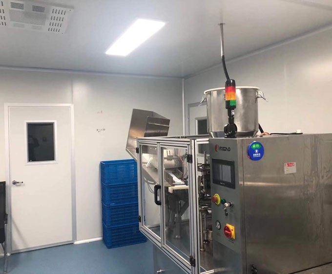
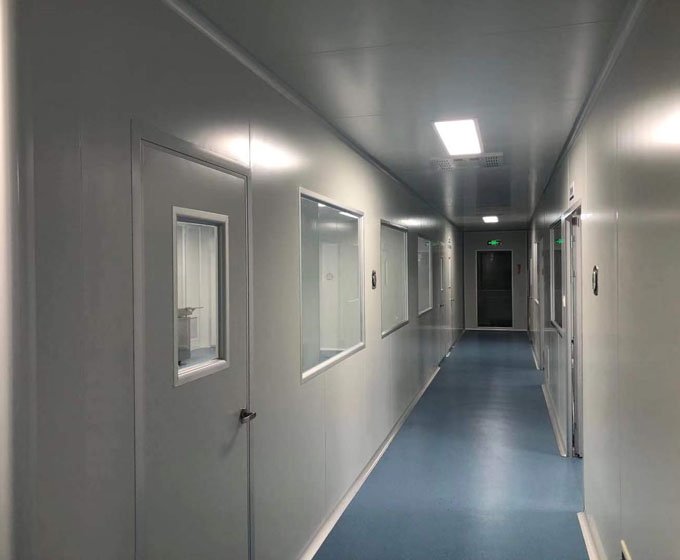
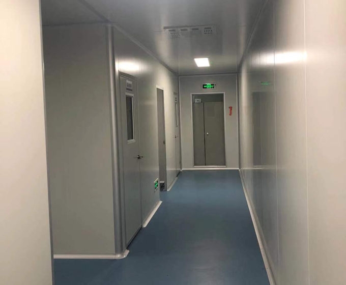
WORKSHOP REAL SCENE
厂房实景
——
 加微信
加微信

Address
济宁高新区柳行办事处东外环路6号(鲁抗医药工业园内)
Mailbox
jiningbolian@126.com
Telephone
0537-2168006
Copyright www.jnblsw.com 558855奔驰宝马 2020 All Rights Reserved ![]()
![]()